- enlarged -
How to use the Output Mixer
- enlarged - |
The Output Mixer control panel software is the main control center of the DSP24 MEDIA 7.1 hardware. The software is used to control the monitoring and the signal levels of your audio PC. Different applications and envrionments (e.g. audio recording vs. multichannel playback) require different monitoring setups. Sometimes you want to listen to the signal you are recording directly (hardware monitoring). Sometimes you want to listen to a modified version of the signal (e.g. processed by an effect processor) or you want to listen to the sounds of the hardware MIDI synthesizer on the MEDIA 7.1 hardware. This means that you need to be able to define what exactly is played through each separate output channel of the hardware. The Output Mixer control panel software allows you to do that; choose the way you like to work.
Patchbay
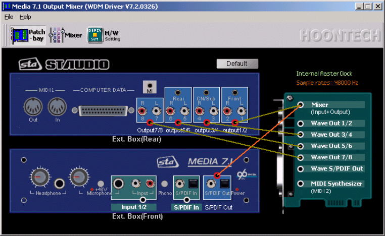
The main screen (Patchbay) of the software that is displayed in the picture on the right shows the connectors on the external box of the MEDIA 7.1 on screen (both the front and rear panels are displayed). The right section of the Patchbay screen symbolizes the I/O interface as addition to the external box. The software allows you to connect the available playback sources (light green background) with the physical outputs (light blue background) virtually on screen.
 The
virtual cables for the outputs cannot be removed but replaced by other connections.
These connections are displayed as straight lines between the red and white
circles. The available output sources (white circles / light green background)
are:
The
virtual cables for the outputs cannot be removed but replaced by other connections.
These connections are displayed as straight lines between the red and white
circles. The available output sources (white circles / light green background)
are:
| • | Mixer; the output signal from the digital mixer on the MEDIA 7.1 hardware (see below) |
| • | Wave Out 1/2; the playback of the wave device ADSP24 Ext. 1/2 Audio Device or channel 1/2 of the ASIO/GSIF driver |
| • | Wave Out 3/4; the playback of the wave device ADSP24 Ext. 3/4 Audio Device or channel 3/4 of the ASIO/GSIF driver |
| • | Wave Out 5/6; the playback of the wave device ADSP24 Ext. 5/6 Audio Device or channel 5/6 of the ASIO/GSIF driver |
| • | Wave Out 7/8; the playback of the wave device ADSP24 Ext. 7/8 Audio Device or channel 7/8 of the ASIO/GSIF driver |
| • | Wave S/PDIF Out; the playback of the wave device ADSP24 Ext. SPDIF Device or channel 9/10 of the ASIO/GSIF driver |
| • | MIDI Synthesizer; the output of the hardware MIDI synthesizer on the DSP24 MEDIA 7.1 (accessed by the MIDI device ADSP24 MIDI2 Device) |
| • | Input 1/2; the input signal from the line, phono or microphone input on the external box |
| • | S/PDIF In; the input signal of the optical or coaxial S/PDIF input on the front panel of the external box |
All of these available signal sources can be connected to the outputs (red circles / light blue background) in the Patchbay window. Just click and hold the left mouse button on the white circle of the signal source and release it on the red circle of the output destination you want to send the signal to. The Output Mixer control panel software will show you which destinations can be reached by the selected signal by changing the color of the possible destinations until the left mouse button is released.
Examples
The following pictures show a few examples of possible Patchbay configurations for certain situations:
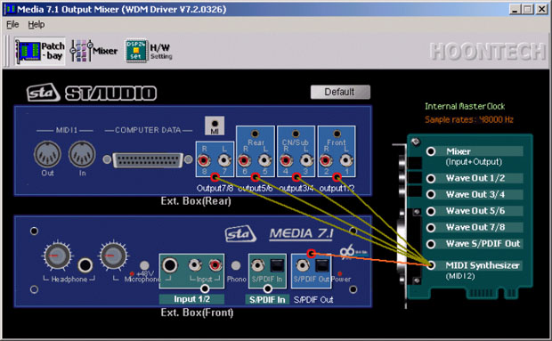
This setup (above) routes the
output signal of the MEDIA 7.1 hardware synthesizer to all analog output channels
and to the S/PDIF output simultaneously.

The configuration on this picture
is used to send out the signal of the digital mixer to the optical and coaxial
S/PDIF output. At the same time, all wave out device channels are sent directly
to their corresponding physical outputs (e.g. for analog 6 or 8ch DVD playback).
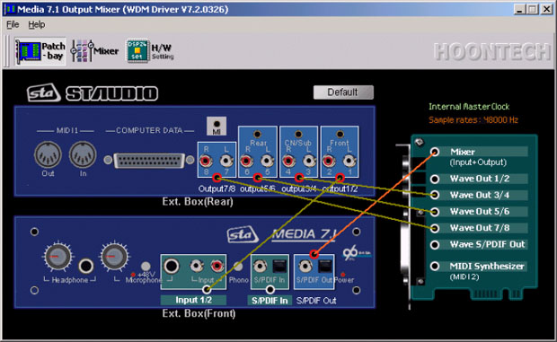
The setup on this picture also
has a connection between the digital mixer and the S/PDIF output. Additionally
it is used to send out the signal from the physical analog input 1/2 to output
1/2 (no latency / realtime) to allow direct monitoring of the incoming signal.
Digital Mixer
With the Mixer section inside the Output Mixer software you can control all incoming and outgoing signals. Open it by clicking on Call Mixer in the menu of Output Mixer or by clicking the Mixer button.
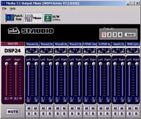
Note: The digital Mixer will only change the audible signal for monitoring purposes. You can either output it through the analog output 1/2 and/or through the S/PDIF outputs on the external box (as connected in the Patchbay). When you are recording an input signal, the digital Mixer does not change the signal level. This ensures that you are always recording with best possible audio quality without reduction of the dynamic range. All professional cards operate in this way.
| Master |
Controls the output volume of the digital Mixer. The signal controlled here will be played through the analog output 1/2 and/or through the S/PDIF output. It is even possible to resample the output signal of the digital Mixer internally using the wave device ADSP24 Digital Mixer (n) or channel 11/12 of the ASIO driver. You can control the the volume of the left and right channels independandly. Muting the signal is possible as well. |
| Wave (1/2 to 7/8) | In the Wave section you can control the volume of the playback signal (for the devices ADSP24 Ext. x/x Audio Device or the channels 1~8 of the ASIO and GSIF driver). Muting each channel is possible (M button). Also you can control the panning independant for the left and right channel of each stereo device. |
| S/PDIF Out | In the S/PDIF Out section you can control the volume of the signal of the device ADSP24 Ext. SPDIF Device or channel 9/10 of the ASIO and GSIF driver. Muting the left and right channels is possible independantly. |
| S/PDIF In | This section controls the signal from the digital S/PDIF input of the card. Muting the left and right channels is possible independantly. |
| Input 1/2 | This sections controls the volume of the analog input channel (line, phono, microphone). Muting the left and right channels is possible independantly. |
| MIDI Synthesizer | This sections controls the volume of the hardware MIDI Synthesizer that is accessed by the ADSP24 MIDI2 Device MIDI device. Muting the left and right channels is possible independantly. |
 Presets:
The digital Mixer allows you to save four presets for quick access
in the upper right corner. You can easily load them by clicking on the 1,
2, 3 or 4 button. To save the current settings under the
selected number, simply press Save.
Presets:
The digital Mixer allows you to save four presets for quick access
in the upper right corner. You can easily load them by clicking on the 1,
2, 3 or 4 button. To save the current settings under the
selected number, simply press Save.
Hardware Settings
The Hardware Settings [1] dialog can be accessed via the H/W setting button. Check our separate KB article with more information.
|
|
last updated: 07/12/2002 author: Claus Riethmüller
|
|
| References to other documents or external websites |
|
[1]
The Hardware Settings dialog,
ST Audio Knowledge Base
|
|
|