- enlarged -
How to use External Links
Introduction
- enlarged - |
We sometimes get asked, why the user interface of the DSP24 series looks "confusing" or is "hard to understand". This text will explain the function of the External Links software and shows that the usage of the software is actually much more simple as it might look initially.
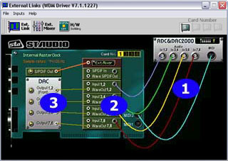
External Links is the main control center of the DSP24 PCI card with the look&feel of a patchbay. You use it to setup the hardware after the installation and to control the signal routing for your specific software and studio setup.
As the DSP24 card can be used in different configurations (e.g. the DSP2000 C-Port or DSP3000 M-Port packages) and provides huge expandibility (just think about the DM III or the DS2000 which can be added later via the H-BUS interface [1]), a manual one-time setup is needed to 'inform' the driver of the hardware options you have installed in your setup.
External Links also controls the monitoring of your PC based studio with the DSP24 card. Different studio envrionments (e.g. analog mixing desk vs. PC as digital mixer) require different monitroing setups. Sometimes you want to listen to the signal you are recording at the moment. Sometimes you want to listen to a modified version of the signal (e.g. processed by an effect processor) or you do want to listen to a completly different audio track while recording. This means that you need to be able to define what exactly is played through the separate output channels of your audiocard and External Links allows you to do that.
Initial setup
 As
mentioned, you need to perform some one-time configuration steps to be able
to use the different hardware options. You do this via Inputs>Add Inputs
in the menu:
As
mentioned, you need to perform some one-time configuration steps to be able
to use the different hardware options. You do this via Inputs>Add Inputs
in the menu:
| • | select MK II input if you are using a DSP24 MK II PCI-card |
| • | select Digital Station 2000 if you have connected the DS2000 ADAT-/TDIF-interface |
| • | select ADC&DAC2000 if you have connected an ADC&DAC2000 (e.g. you are using a DSP2000 C-Port system) |
| • | select ADC&DAC3000 if you have connected an ADC&DAC3000 (e.g. you are using a DSP3000 M-Port system) |
| • | select XG DB I if you are using the digital S/PDIF or AES/EBU input of the card [2] |
| • | select SoundTrack DigitalAudio(Master) if you have installed a ST D_A 4ch/16ch soundcard from Hoontech [3] in your PC |
| • | select Digital Modulator III if you have connected a DM III to the card |
| • | select ADC III if you have connected an ADC III to the card |
| • | General Box is used for possible future extensions or if you use one of the older Hoontech [3] 5-1/4" ADC units |
 The
right section of the External Links window will now display what you
have selected in the menu. By right clicking on a box on screen you can select
the Box Number for the rackmountable external boxes. Please make sure
that the number (displayed as a yellow number) is identical with the number
you have selected on the rackmountable hardware via the DIP-switches on the
right side panel. If you use an ADC&DAC2000
for example, the first DIP switch is set moved up, all others down. This means
the box number is 1 and needs to be selected inside External Links as
well. This allows you optionally to use several external boxes at the same time
via the H-BUS [1] interface
of your DSP24 card as every box has a unique number.
The
right section of the External Links window will now display what you
have selected in the menu. By right clicking on a box on screen you can select
the Box Number for the rackmountable external boxes. Please make sure
that the number (displayed as a yellow number) is identical with the number
you have selected on the rackmountable hardware via the DIP-switches on the
right side panel. If you use an ADC&DAC2000
for example, the first DIP switch is set moved up, all others down. This means
the box number is 1 and needs to be selected inside External Links as
well. This allows you optionally to use several external boxes at the same time
via the H-BUS [1] interface
of your DSP24 card as every box has a unique number.
 You
continue by connecting the inputs virtually on screen. When you click and hold
the left mouse button on a virtual connector inside the software, all the connection
options will be highlighted with an orange color. The picture on the left side
shows an ADC&DAC2000
with the inputs 1 to 6 already in use, as well as the MIDI input. Currently
the connection for inputs 7 and 8 is beeing made (as the connector is highlighted).
The box number in this example is 1, which is the default number (the picture
even shows how the DIP-switches should look like on the hardware). As you can
see, the input signal routing is always done in stereo-pairs. The reason is
the internal handling of audio I/O channels in stereo-pairs of the Windows operating
system (MME devices). Most professional audio applications allow you to select
/ control the two different mono channels of a stereo-pair individually of course.
You
continue by connecting the inputs virtually on screen. When you click and hold
the left mouse button on a virtual connector inside the software, all the connection
options will be highlighted with an orange color. The picture on the left side
shows an ADC&DAC2000
with the inputs 1 to 6 already in use, as well as the MIDI input. Currently
the connection for inputs 7 and 8 is beeing made (as the connector is highlighted).
The box number in this example is 1, which is the default number (the picture
even shows how the DIP-switches should look like on the hardware). As you can
see, the input signal routing is always done in stereo-pairs. The reason is
the internal handling of audio I/O channels in stereo-pairs of the Windows operating
system (MME devices). Most professional audio applications allow you to select
/ control the two different mono channels of a stereo-pair individually of course.
As you have seen, there is no option (and no need!) to select anything to setup the outputs of the card. The DSP24 hardware will automatically recognize units with outputs such as the DAC III. The initial setup for External Links is also described in the manual of the DSP24 more detailed. As long as you do not change this setup, the software will always remember your settings.
What is displayed by External Links?
 After
we have performed the needed one-time steps to 'tell' the DSP24 driver what
hardware options we have installed, we can check what else we can do with the
software. The software is divided into three main sections (yes, from right
to left):
After
we have performed the needed one-time steps to 'tell' the DSP24 driver what
hardware options we have installed, we can check what else we can do with the
software. The software is divided into three main sections (yes, from right
to left):
| 1. | All the available inputs are displayed on the right side of the window. You can connect them virtually on screen when needed. |
| 2. | The section in the middle symbolizes the I/O interface on the DSP24 card. The virtual connectors on the right side (gray) are representing the input channels of the card, the connectors on the left side (white) are the available sources for the outputs. |
| 3. | The output channels of the card are displayed on the left side of the window. The digital output (S/PDIF Out) and also the 8 channels of the external boxes are displayed under with the DAC headline (Digital to Analog Converter) |
The virtual cables on screen show you the signal routing for all inputs and all inputs. The input cables on the right side can be removed and added as needed. The virtual cables for the outputs (which mainly control the monitoring) cannot be removed but replaced by other connections. Because of that, the connections are displayed as straight lines.
 The
five gray virtual connectors in the middle section are corresponding to the
MME wave devices (and the ASIO-driver) you are using inside your application.
The
five gray virtual connectors in the middle section are corresponding to the
MME wave devices (and the ASIO-driver) you are using inside your application.
The first one (S/PDIF In) corresponds to the wave device ADSP24 S/PDIF Input (n) (where n is the card number when multiple DSP24 cards are installed) or to channel 9/10 of the ASIO driver. Under Windows 2000/XP, the name of the wave device is ADSP24 Ext. SPDIF Device.
The others (Input x,y) correspond to the wave devices ADSP24 Ext. (n) Input x/y or to channels x/y of the ASIO driver (where x+y are the numbers of the channels). Under Windows 2000/XP, the names of these wave devices are ADSP24 Ext. x/y Audio Device.
This means for example: if you record using ADSP24 Ext. (1) Input 5/6, you will get the signal from the yellow virtual cable which would be the input signal from the inputs number 5 and 6 (of the first DSP24 if there are several cards installed).
 On
the left side of the middle section, the available output sources are listed
with white connectors. You can see:
On
the left side of the middle section, the available output sources are listed
with white connectors. You can see:
| - | S/PDIF In; the signal from the gray input connector on the right |
| - | Wave S/PDIF Out; the playback of the wave device ADSP24 S/PDIF Out (n) (Windows 9x/Me), ADSP24 Ext. SPDIF Device (Windows 2000/XP) or channel 9/10 of the ASIO/GSIF driver |
| - | Input 1,2; the signal from the gray 1,2 input on the right |
| - | WaveOut 1,2; the playback of the wave device ADSP24 Ext. WaveOut 1/2 (n) (Windows 9x/Me), ADSP24 Ext. 1/2 Audio Device (Windows 2000/XP) or channel 1/2 of the ASIO/GSIF driver |
| - | Input 3,4; the signal from the gray 3,4 input on the right |
| - | WaveOut 3,4; the playback of the wave device ADSP24 Ext. WaveOut 3/4 (n) (Windows 9x/Me), ADSP24 Ext. 3/4 Audio Device (Windows 2000/XP) or channel 3/4 of the ASIO/GSIF driver |
| - | Input 5,6; the signal from the gray 5,6 input on the right |
| - | WaveOut 5,6; the playback of the wave device ADSP24 Ext. WaveOut 5/6 (n) (Windows 9x/Me), ADSP24 Ext. 5/6 Audio Device (Windows 2000/XP) or channel 5/6 of the ASIO/GSIF driver |
| - | Input 7,8; the signal from the gray 7,8 input on the right |
| - | WaveOut 7,8; the playback of the wave device ADSP24 Ext. WaveOut 7/8 (n) (Windows 9x/Me), ADSP24 Ext. 7/8 Audio Device (Windows 2000/XP) or channel 7/8 of the ASIO/GSIF driver |
All of these available signal sources can be connected to the outputs on the left side of the External Links window.
Monitoring
For each stereo channel pair it is possible to activate direct monitoring (without any latency). As in the example on these two pictures, you simply do it by connecting Input 1,2 to Output 1,2. This means that the signal that comes in onthe input channel 1 & 2 is sent directly to the output channel 1 & 2 without any latency / delay. If you use the DSP2000 C-Port, this example would allow you to send out monitor signals of a microphone (connected to Input 1,2) to the headphone of the singer (connected to the headphone output of the external box). The signal you play inside your application via channel 1 & 2 is not audible now of course!
The second picture shows the alternative: if you connect WaveOut 1,2 with Output 1,2, the playback from your audio application is audible via the first stereo output channel. The signal from the input is not audible at the same time!
External Mixer
 The
limitation of these two options for monitoring (which is a limitation of many
professional audiocards) is that you cannot hear the input and output signal
simultaneously. If you use an analog (or digital) mixer that is connected to
both the inputs and the outputs of the DSP24 card, you can monitor via the mixer
so that is no problem. The DSP24 hardware however has a built-in digital mixer
so you do not really need an external mixing desk. This function is called External
Mixer (easy to remember!) and as the input and playback signals, you can
connect it to Output 1,2 as shown on the picture (on the right).
The
limitation of these two options for monitoring (which is a limitation of many
professional audiocards) is that you cannot hear the input and output signal
simultaneously. If you use an analog (or digital) mixer that is connected to
both the inputs and the outputs of the DSP24 card, you can monitor via the mixer
so that is no problem. The DSP24 hardware however has a built-in digital mixer
so you do not really need an external mixing desk. This function is called External
Mixer (easy to remember!) and as the input and playback signals, you can
connect it to Output 1,2 as shown on the picture (on the right).
If the External Mixer is connected to Output 1,2 (or alternativly to S/PDIF Out), all input and all playback signals are audible simultaneously. When you open the External Mixer (just click on the Ext.Mixer button), you can set the volume for each playback and input channel independandly. This allows you to create your own mix completly digitally inside your PC without the need of external mixing equipment and without the need for special software from third parties. This final mix can be digitally resampled using the ADSP24 (n) Digital Mixer MME wave device or channel 11/12 of the ASIO 2.0 driver.
Internal / External Master Clock
![]() When
you are recording from a digital source (usually from S/PDIF In which
is connected to the XG DB I [2]
via the ADSP24 S/PDIF Input (n) device) it is important that the synchronisation
is made correctly. The current synchronisation setting is displayed in the upper
left corner. Internal Master Clock shows that the DSP24 PCI card is responsible
to supply the samplerate for all recording and playback operations. As soon
as you connect the virtual cable from the XG DB I [2]
on the right side of External Links, the sync is changed to External
Master Clock to allow clean recordings from the S/PDIF or AES/EBU input.
Please note that it is very important that an active device is connected to
the digital input when the sync is set to external. It is not possible to record
a clean signal from the digital input if you use internal synchronisation ...
also it is not possible to playback and record clean signals (on any in- and
output) if you use external synchronisation without anything connected to the
digital input. In fact, on some systems it is not possible to record and playback
at all with a wrong sync setting! It is important to use this setting very carefully.
It can also be changed in the Hardware Settings [4]
dialog (accesable via the File menu).
When
you are recording from a digital source (usually from S/PDIF In which
is connected to the XG DB I [2]
via the ADSP24 S/PDIF Input (n) device) it is important that the synchronisation
is made correctly. The current synchronisation setting is displayed in the upper
left corner. Internal Master Clock shows that the DSP24 PCI card is responsible
to supply the samplerate for all recording and playback operations. As soon
as you connect the virtual cable from the XG DB I [2]
on the right side of External Links, the sync is changed to External
Master Clock to allow clean recordings from the S/PDIF or AES/EBU input.
Please note that it is very important that an active device is connected to
the digital input when the sync is set to external. It is not possible to record
a clean signal from the digital input if you use internal synchronisation ...
also it is not possible to playback and record clean signals (on any in- and
output) if you use external synchronisation without anything connected to the
digital input. In fact, on some systems it is not possible to record and playback
at all with a wrong sync setting! It is important to use this setting very carefully.
It can also be changed in the Hardware Settings [4]
dialog (accesable via the File menu).
Using multiple DSP24 cards
 The
External Links software allows you to control up to four DSP24 / DSP24 MK II
PCI cards in one system. The Card Number selection (see the picture)
allows you to switch between the different cards. Every card has unique and
individual settings when installed together in one PC.
The
External Links software allows you to control up to four DSP24 / DSP24 MK II
PCI cards in one system. The Card Number selection (see the picture)
allows you to switch between the different cards. Every card has unique and
individual settings when installed together in one PC.
You understand it ...
... but still think the software looks confusing? We believe that the External Links application has a very flexible user interface that allows to control all the functions of the hardware with all the options and upgrade possibilites without being too technical. It is definitly possible to work with the software in a very fast way and it is our experience that most DSP24 users agree that the user interface is in fact very simple (some might add 'after you get used to it'). Of course the look & feel is a matter of personal taste :-)
The following crazy (?) example shows you something of the flexibility behind the External Links software in a specific situation (and it is just one of virtually unlimited setup possibilites):
This setup shows a DSP24 card with an ADC&DAC2000 and a DS2000 as ADAT (or TDIF) interface. The 8 audio input channels from the ADAT- or TDIF-device can be recorded and are sent out mixed together (External Mixer) via the S/PDIF output of the XG DB I [2]. At the same time, the first stereo channel of the ADAT- or TDIF device is copied to all analog output pairs of the ADC&DAC2000 and even sent back via ADAT and TDIF the same way. The sync is set to External Master Clock because the DS2000 provides a digital source. Last but not least, the MIDI input of the first external box is enabled as well.
In this setup, the DSP24 could be used as digital mixer to create a mixdown from the ADAT- or TDIF-recorder to a DAT- or MD- via the S/PDIF output. At the same time, the four stereo analog outputs of the ADC&DAC2000 can be used to monitor the signal (e.g. by different people simultanously).
|
|
last updated: 03/29/2003 author: Claus Riethmüller
|
|
| References to other documents or external websites |
|
[1]
Introduction to H-BUS,
ST Audio Knowledge Base
[2] What is XG DB I?, ST Audio Knowledge Base [3] Hoontech website - makers of the SoundTrack Digital Audio 4ch/16ch soundcard [4] The Hardware Settings dialog, ST Audio Knowledge Base |
|
|