What is XG DB I?
A simple question and a simple answer: the XG DB I is included with the DSP24 and DSP24 MK II cards and is used to provide the S/PDIF and AES/EBU digital I/O connection possibility. The bracket should be installed in an empty opening of the computer case and is connected with an internal 4-pin cable to the audiocard. This text explains the usage of the XG DB I bracket and explains how to send signals via the digital outputs and how to record from the digital input.
Connectors
The following graphic shows the layout of the connectors on the XG DB I:
Digital output
The XG DB I provides three digital output connectors: the optical S/PDIF output, the coaxial S/PDIF output and the AES/EBU output. All of these three outputs will always send out the same audio signal, just in a different format. This means that you can use the different outputs at the same time if needed.
![]() In
order to send out a signal via the S/PDIF output, the MME device ADSP24 S/PDIF
Out (n) or ASIO/GSIF channel 9/10 is used. The signal will be played 1:1
bit-identically via all the digital outputs as long as you have connected Wave
S/PDIF Out with S/PDIF Out inside the External Links [1]
software as shown in this picture. The signal will be played with the samplerate
and bit-depth of the file you are playing.
In
order to send out a signal via the S/PDIF output, the MME device ADSP24 S/PDIF
Out (n) or ASIO/GSIF channel 9/10 is used. The signal will be played 1:1
bit-identically via all the digital outputs as long as you have connected Wave
S/PDIF Out with S/PDIF Out inside the External Links [1]
software as shown in this picture. The signal will be played with the samplerate
and bit-depth of the file you are playing.
 You
can also output the signal of the External Mixer. In that case, you will
get a mixed signal of all input channels (incl. the signals from the external
boxes) and all playback channels from your application via the digital output.
The signal will be played with the samplerate that was selected inside the Hardware
Settings [2] dialog.
To send out the mixer signal, connect Ext.Mixer with S/PDIF Out.
Of course the output signal will no longer be bit-identical if you just playback
a stereo channel as it is processed by the mixer and mixed with the input signals.
You can use this setting in order to monitor via an external DAC or to send
out your master to a DAT recorder for example (when working with the External
Mixer).
You
can also output the signal of the External Mixer. In that case, you will
get a mixed signal of all input channels (incl. the signals from the external
boxes) and all playback channels from your application via the digital output.
The signal will be played with the samplerate that was selected inside the Hardware
Settings [2] dialog.
To send out the mixer signal, connect Ext.Mixer with S/PDIF Out.
Of course the output signal will no longer be bit-identical if you just playback
a stereo channel as it is processed by the mixer and mixed with the input signals.
You can use this setting in order to monitor via an external DAC or to send
out your master to a DAT recorder for example (when working with the External
Mixer).
As third alternative it is also possible to route any of the input signals directly to the digital output using the External Links [1] software. Just make the corresponding setting (e.g. Input 1/2 to S/PDIF Out).
Digital input
 Unlike
with the digital outputs, it is not possible to use the four digital inputs
of the XG DB I at the same time: the optical S/PDIF input, the coaxial S/PDIF
input, the internal 2pin CD-ROM input and the AES/EBU input are all assigned
to the same stereo input channel of the DSP24 / DSP24 MK II card.
Unlike
with the digital outputs, it is not possible to use the four digital inputs
of the XG DB I at the same time: the optical S/PDIF input, the coaxial S/PDIF
input, the internal 2pin CD-ROM input and the AES/EBU input are all assigned
to the same stereo input channel of the DSP24 / DSP24 MK II card.
To use the digital input, you have to activate it inside External Links [1] by adding the XG DB I as available input and by connecting the virtual S/PDIF input cable. After that you can record the input signal with the device ADSP24 S/PDIF Input (n) or via ASIO channels 9/10. Please note that adding this virtual cable automatically changes the sync of the DSP24 card (see below).
Please be careful when you are using the internal digital input for CD-ROM drive signals. Many CD-ROM drives are always sending out a sync signal, even if you do not playback an audio CD at the moment. This means (as the different inputs cannot be used simultanously as mentioned) that the coaxial + optical S/PDIF and AES/EBU inputs are not available in that case. Please only connect the CD-ROM drive internally to the card / the XG DB I if you know (probably after testing) that it does not block the digital input or if you do not use the S/PDIF and AES/EBU inputs at all.
Synchronisation
![]() When
you are recording from a digital source via the ADSP24 S/PDIF Input (n)
device it is important that the synchronisation is made correctly. The current
synchronisation setting is displayed in the upper left corner of External
Links [1]. Internal
Master Clock shows that the DSP24 PCI card is responsible to supply the
samplerate for all recording and playback operations. As soon as you connect
the virtual cable from the XG DB I as described above, the sync is changed to
External Master Clock to allow clean recordings from the S/PDIF or AES/EBU
input. Please note that it is very important that an active device is connected
to the digital input when the sync is set to external. It is not possible to
record a clean signal from the digital input if you use internal synchronisation
... also it is not possible to playback and record clean signals (on any in-
and output) if you use external synchronisation without anything connected to
the digital input. In fact, on some systems it is not possible to record and
playback at all with a wrong sync setting! It is important to use this setting
very carefully. It can also be changed in the Hardware Settings [2]
dialog. Also double check in the Hardware Settings dialog (when recording
from S/PDIF or AES/EBU) that the samplerate has been recognized correctly (you
can also force it to a certain samplerate if needed).
When
you are recording from a digital source via the ADSP24 S/PDIF Input (n)
device it is important that the synchronisation is made correctly. The current
synchronisation setting is displayed in the upper left corner of External
Links [1]. Internal
Master Clock shows that the DSP24 PCI card is responsible to supply the
samplerate for all recording and playback operations. As soon as you connect
the virtual cable from the XG DB I as described above, the sync is changed to
External Master Clock to allow clean recordings from the S/PDIF or AES/EBU
input. Please note that it is very important that an active device is connected
to the digital input when the sync is set to external. It is not possible to
record a clean signal from the digital input if you use internal synchronisation
... also it is not possible to playback and record clean signals (on any in-
and output) if you use external synchronisation without anything connected to
the digital input. In fact, on some systems it is not possible to record and
playback at all with a wrong sync setting! It is important to use this setting
very carefully. It can also be changed in the Hardware Settings [2]
dialog. Also double check in the Hardware Settings dialog (when recording
from S/PDIF or AES/EBU) that the samplerate has been recognized correctly (you
can also force it to a certain samplerate if needed).
In a special application where you have connected the card to another device (e.g. a digital mixer) via the digital output and the digital output at the same time, you can (and must!) decide which of the two devices will be responsible for the sync. If the external device should be responsible for the sync, set it to internal clock and set the DSP24 PCI card to External Master Clock. If the PC should be responsible for the sync, set the card to Internal Master Clock and make sure your external device is using external clock. In any case, please refer also to the manual of the device you have connected this way to the XG DB I. If these settings are not done properly, you will most likely get problems with noise or crackles.
AES/EBU
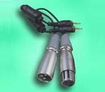 You
might have wondered how in the world the 1/8" connectors on the XG DB I
are supposed to be AES/EBU I/O ports when AES/EBU usually is using XLR connectors.
The problem is the missing space for XLR connectors of course. The 1/8"
to XLR connectors are available optionally or are included by default with your
DSP24 / DSP24 MK II - please check this with the local distributor as there
are differences in the different international markets. You can see the adapter
set on the picture on the right side. As TRS to XLR adapters are often also
used in other places in a studio envrionment, you might probably even already
have correct adapters. Here is the pin-layout:
You
might have wondered how in the world the 1/8" connectors on the XG DB I
are supposed to be AES/EBU I/O ports when AES/EBU usually is using XLR connectors.
The problem is the missing space for XLR connectors of course. The 1/8"
to XLR connectors are available optionally or are included by default with your
DSP24 / DSP24 MK II - please check this with the local distributor as there
are differences in the different international markets. You can see the adapter
set on the picture on the right side. As TRS to XLR adapters are often also
used in other places in a studio envrionment, you might probably even already
have correct adapters. Here is the pin-layout:
|
XLR
|
1/8"
or 1/4"
|
Signal
|
| 1 | Sliver | GND |
| 2 | Tip | Bal+ / hot |
| 3 | Ring | Bal- / cold |
If you never heard about AES/EBU: simplified, AES/EBU is the professional (balanced) version of the S/PDIF format to transfer stereo signals digitally using high-quality 3-wire cables, even for longer connections if needed.
|
|
last updated: 09/07/2001 author: Claus Riethmüller
|
|
| References to other documents or external websites |
|
[1]
How
to use External Links,
ST Audio Knowledge Base
[2] The Hardware Settings dialog, ST Audio Knowledge Base |
|
|